OPEN: MON - FRI 8AM - 5PM
Check our current lead time for Cut & Edge orders COLLECTIONS: 8AM - 4PM

Step-by-step guide.

How to Create a DXF File in Inkscape for CNC Cutting

Understanding DXF files for CAD and CNC cutting.

What Is a DXF File?

A DXF (Drawing Exchange Format) file is a type of vector drawing file. It stores shapes as precise lines and curves using exact measurements.

DXF files are commonly used in CAD and CNC machining because they allow machines to follow accurate paths. When you send a DXF file to a CNC service, the machine reads the vector lines and cuts exactly along those paths.

In simple terms:
A DXF file tells the CNC machine where to move and where to cut.

Why CNC Machines Require Vector Paths

CNC routers cannot read images such as JPG, PNG, or PDF files that contain pixels. They only understand vector paths. Each vector line becomes a toolpath. The CNC machine follows the centre of that path using a rotating cutting tool. If your file contains:

  • Images instead of vectors
  • Open or broken lines
  • Overlapping shapes
  • Incorrect scale
The machine cannot cut the part correctly. That’s why clean vector geometry is essential.

CNC Machines Require Vector Paths

Step 1: Install and Open Inkscape

Inkscape is a free vector drawing program used to create 2D designs for CNC cutting. If you do not already have it installed:

  1. Go to www.inkscape.org
  2. Click Download
  3. Choose the correct version for your system (Windows, Mac or Linux)
  4. Follow the installation steps
The installation only takes a few minutes.

Step 2: Set Units Properly

This is the most common cause of incorrect CNC cuts. If your units are wrong, your parts will be the wrong size.

Follow these steps:

  • File → Document Properties
  • Set Display Units to mm
  • Set Custom Size Units to mm
  • Check Scale = 1.0
  • Set precision (2–3 decimal places)

Why this matters?

CNC machines work in real-world measurements, not pixels. If your document is set to pixels, your design may export at the wrong size. For example, a 600mm cabinet panel drawn in pixels may not cut at 600mm which can cause parts not to fit during assembly. Always design at 1:1 scale.

Set Document Units Properly

Step 3: Set the Page Size to Match Your Material Sheet

Although Inkscape allows you to draw anywhere on the canvas, setting the page size helps you design more accurately.

How to set page size:

  • Go to File → Document Properties
  • Under Custom Size, enter your sheet width and height in mm
The white rectangle now represents your material sheet.

Why set the page size?

  • It helps you visualise your sheet size.
  • It prevents you from designing parts larger than your material.
  • It makes layout and spacing easier to plan.
For example, common sheet sizes in the UK include:
  • 2440 × 1220mm (8×4 sheet)
  • 3050 × 1220mm (larger sheets)
If you are cutting from an 8×4 sheet, set your page to 2440mm width and 1220mm height.

Important:

The page boundary is not a cut line. CNC machines do not cut the page background. Setting the page size is simply a visual guide to help you design accurately and realistically.

Inkscape - Setting the page size

Step 4: Drawing Correct Vector Paths

CNC machines only cut along vector lines, not images or visual effects. Make sure your design follows these rules:

  • Use shapes or the Bezier tool to create lines and curves
  • Avoid bitmap images (JPG, PNG) — machines cannot cut them
  • Keep everything 2D (very important) — no 3D effects, gradients, shadows, or fills
  • Draw clean paths — the machine will follow the centre of each vector line
Think of your vector paths as a roadmap for the CNC tool. Only the lines you draw will be cut.

Step 5: Convert Everything to Paths

Before exporting your DXF, every object in your design must be converted to paths. CNC machines cannot cut text or shapes unless they are paths.

  1. Ungroup any grouped objects:
    • Select the object → Object → Ungroup
  2. Convert to paths:
    • Select your object → Path → Object to Path

Why this matters:

  • Text must be converted so it doesn’t rely on fonts.
  • Shapes must be converted so the CNC machine sees the outlines.
  • Prevents missing letters or substituted fonts when your file is opened on another computer.

Workflow summary:

Object → Ungroup → Object to Path. Now your design is fully vector-based and ready for CNC export.

Convert to paths

Step 6: Remove Fills & Set Stroke Properly

CNC machines only follow the centre of vector lines. Fills and stroke thickness do not affect cutting.

  • Remove all fills from your objects — only the outline matters
  • Set stroke width to a thin line (hairline, 0.01–0.1mm)

Why this matters:

  • Fills are ignored by CNC machines
  • Thick strokes do not increase the cut width. The tool follows the centreline only

Pro tip:

Use a thin stroke so your design is easy to see on screen without affecting the final cut.

Remove Fills & Set Stroke

Step 7: Ensure All Paths Are Closed

For CNC cutting, every path must form a complete loop. Open paths can cause incomplete or broken cuts.

  1. Use the Node Tool to inspect your shapes
  2. Look for gaps or loose ends in the paths
  3. If a path is open, select the end nodes → Join Selected Nodes

Why this matters:

Closed paths ensure the CNC machine cuts each part completely and accurately. Open paths may result in missing edges or unfinished cuts.

Close paths

Step 8: Remove Duplicate or Overlapping Lines

Duplicate or overlapping lines are a common cause of problems in CNC cutting.

Why it matters:

  • CNC machines will cut overlapping lines twice
  • Waste cutting time

How to fix:

  • Select all objects → Path → Combine to merge overlapping lines
  • Or inspect manually in Wireframe view to see hidden duplicates
Cleaning up overlaps ensures a smooth cut and avoids unnecessary material waste.

Combine duplicate lines

Step 9: Understand Inside Corners (Tool Diameter Rule)

CNC cutting tools are round, which means they cannot cut perfectly sharp internal corners.

Key concepts:

  • Internal corner radius: The smallest radius the tool can cut inside a corner
  • Dog bones or T-bones: Extra material cut away at inside corners to allow square tabs to fit

Why this matters:

If your design includes slots or recesses for a square tab, the corners will be slightly rounded unless you add relief cuts. Without this, parts may not fit together properly.

Tip:

Always check inside corners and add dog bones or T-bones where square edges are needed.

Understand Inside Corners

Step 10: Check Minimum Detail Size & Tool Limits

CNC machines have physical limitations. Very small details or thin sections may not cut properly or can break during machining.

Things to watch for:

  • Tiny details may be too fragile to cut
  • Thin bridges between shapes can snap
  • Internal cut-outs need enough space for the tool to fit

General guidance:

  • Minimum slot width = your tool diameter
  • Avoid extremely tight internal radii that the tool cannot reach
Following these rules ensures your parts are strong, precise and cut correctly.

Check Minimum Detail Size & Tool Limits

Step 11: Check Dimensions Accurately

Before exporting your DXF, make sure every measurement is correct.

  • Use Inkscape’s Measuring Tool to check all dimensions
  • Confirm width and height of each part
  • Check hole positions and spacing between features
  • Double-check gaps and clearances for joinery

Reminder:

Always design at final size (1:1 scale). Do not rely on scaling the design later. Mistakes at this stage will carry through to the finished part.

Check Dimensions Accurately

Step 12: Save as DXF (Correct Format)

Once your design is ready, you need to save it in the correct DXF format for CNC machines.

  1. Go to File → Save As
  2. Choose Desktop Cutting Plotter (AutoCAD DXF R2013)

Recommended settings:

  • Use LWPOLYLINE (lightweight polylines for cleaner paths)
  • Base unit = mm
  • Disable splines if the option appears

Why DXF R2013:

  • Newer DXF versions (2018, 2020, etc.) can introduce features that CNC software often doesn’t support, such as advanced splines, text formatting or 3D data.
  • These extra features can cause missing lines, incorrect scaling or errors when the file is imported.
  • DXF R2013 keeps the file simple, compatible and reliable, while preserving all 2D vector paths your CNC machine needs.
Saving in R2013 ensures your file is fully compatible across most CNC software and cuts exactly as designed.

Save as DXF file

Step 13: Re-Open & Validate

Validating your DXF file is crucial before sending it for CNC cutting.

  1. Close the file after saving
  2. Re-open the DXF in Inkscape or another program
  3. Check the scale. Ensure all parts are the correct size
  4. Inspect for missing elements — make sure nothing disappeared during export
  5. Check line joins — all paths should still be closed and properly connected

Optional:

  • Open the DXF in a free DXF viewer to double-check everything before submission
This final check helps avoid errors, delays and wasted material.

Re-Open & Validate

Step 14: Final CNC Submission Checklist

Before sending your DXF to a CNC service, make sure your file passes this checklist:

  • ✅ Units set to millimetres (mm)
  • ✅ Design drawn at full size (1:1 scale)
  • ✅ All objects converted to paths (including text and shapes)
  • ✅ No fills — outlines only
  • ✅ All paths fully closed
  • ✅ No duplicate or overlapping lines
  • ✅ Inside corners checked (dog bones or reliefs added if needed)
  • ✅ Dimensions and hole positions verified
  • ✅ Material thickness specified
  • ✅ Tool size and cutting limits considered

Final Checklist for DXF file

Designing for Cabinet Joinery in Inkscape

For those looking to take their designs to the next level, you can prepare CNC-ready joinery directly in Inkscape. This section covers common features used by cabinet makers and shopfitters.

Key joinery elements to include:

  • Hinge hole layout – Accurately position holes for hinges so doors align perfectly
  • Multiple drillings – Use different layers or colors for holes of different diameters or depths
  • Grooves and pockets – Add comments in your DXF specifying cut depth (e.g., 5 mm or 10 mm)
  • Shelf pin spacing – Mark consistent holes for adjustable shelves
  • Dados and rebates – Cut grooves and recesses for shelves, panels and drawer bottoms
  • Back panel recess – Ensure the back panel slot is correctly sized and aligned

Pro tip:

Use layers or colours with depth annotations in Inkscape so your CNC operator knows exactly how to cut, making your DXF fully CNC-ready and assembly faster and more accurate.

Cabinet Joinery in Inkscape

Common Mistakes

Even experienced designers sometimes make avoidable errors when preparing DXF files for CNC. Avoid these pitfalls to save time, material and frustration:

  • Sending PDFs or images instead of DXF – CNC machines cannot read pixel-based files.
  • Forgetting the outer profile – Parts won’t cut correctly without a defined edge.
  • Designing in inches by mistake – CNC machines expect millimetres; scaling errors can ruin parts.
  • Using stroke width to represent depth – Depth must be communicated via annotations, layers, or colours.
  • Forgetting to label parts – Helps assembly, especially for multiple panels or complex projects.
  • Not accounting for kerf – Tool width removes material; slots and joints may end up too tight.
  • Tight tolerance joinery without clearance – Slots, tabs, and internal corners need a small gap for proper fit.
Following these rules ensures your file is clean, CNC-ready and avoids costly mistakes on the machine.

Common Mistakes

Precision CNC cutting made simple.

Ready to Bring Your Designs to Life?

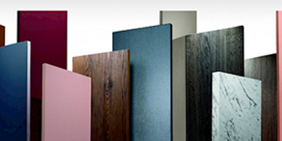
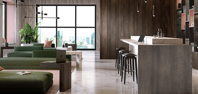
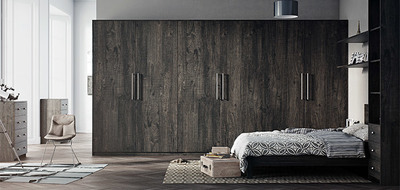
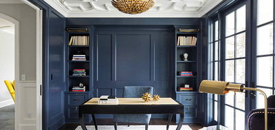
Whether you’re a cabinet maker, designer or DIYer, our CNC cutting service delivers precision-cut parts every time. From furniture components to bespoke panels, we work with a wide range of materials, thicknesses and finishes to match your project requirements.

Fast, accurate and fully CNC-ready. Upload your DXF and let us handle the cutting.

Get Your CNC Parts Cut Today

DXF Design FAQs

Can I use JPG, PNG, or PDF files instead of DXF?
Can I include multiple layers or colors in my DXF?
How do I account for the CNC tool’s width?
Can I use text in my DXF file?
Do I need to label parts in my DXF?
How do I handle inside corners for square tabs?
What’s the minimum feature size I can cut?
Can DXF files be used for laser, plasma and router CNC machines?